Bicycle iPhone and USB Charging – The Charging Circuit
Okay, here’s the situation: I need to charge a pair of Lithium-Iron Phosphate batteries with the AC output of a bicycle dynamo, which varies in voltage depending on how fast I ride. I would also like to charge the batteries when I’m off my bike and in civilization. I need a charging circuit that can do the following:
- Accept an AC input that varies from 1 to 20 volts
- Accept the DC input from a wall adapter of some kind – 12 volts perhaps
- Charge batteries up to 7.4 volts (The charge limit of LiFePO4 battery cells x 2)
- Stop charging when the batteries are at 7.4 volts or above (very important!)
- Use the power efficiently (since there won’t be a lot of it)
Listed together, these requirements are quite daunting to the novice engineer like myself. Especially when an online search reveals only complicated or incomplete solutions:
- The “Ride And Charge” system, involving a special add-on to a bike light. A very old-school and incomplete solution.
- Pawel Danielewicz’s regulator and charging circuit – elegant and complete, but beyond my ability to assemble.
- Sheldon Brown’s brute-force solution of wiring a dynamo directly to a rectifier and a battery, which is quite clever in principle, but very bad for LiFePO4 or other Lithium-style cells.
- A USB charger that does not involve batteries, by JeffB and his teammates. Popular on the internet search engines, but an incomplete and hugely inefficient solution.
- Mark Hoekstra’s bottle and crank solution featured in Make magazine. Extra points for style, but not suited to my batteries or power requirements.
- Mark and Ju’s multi-charger box, an amazingly complete solution that is both more than I need and beyond my abilities.
- The DynaLader USB2, a dynamo-powered battery charger with a USB port attached. Similar to what I’m building. If it had more than one port, was more rugged, and charged Lithium-Ion style cells, I’d probably buy it.
So what’s a relative novice like myself going to do? Keep searching on the internet! After much toil I eventually came across a project assembled by Alex Lockhart that showed the way to go. (Do read his travelogue, it’s full of good thoughts and ideas.)
The TuneCharger
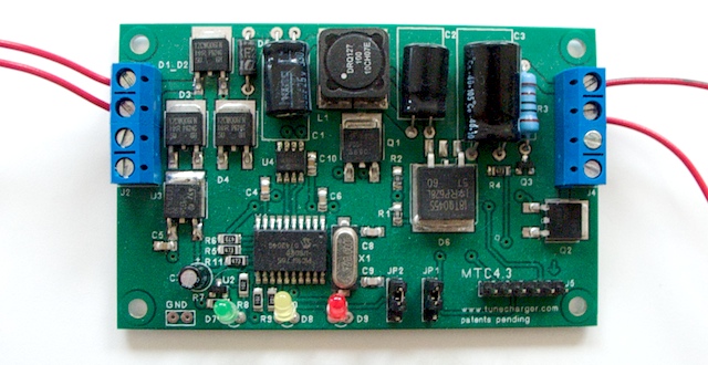
The centerpiece of his system is a small board from France known as the TuneCharger. (Alex’s page has an excellent description of how it works.) This board elegantly satisfies all five items on my list of requirements. It even pulse-charges the batteries, which is the most efficient way to do it. It’s as simple as plugging the hub or wall adapter into one end, and plugging the battery and regulator into the other end. The board has also been successfully tested with LiFePO4 batteries by its creators.
As the Axeon Power page describes it, “Pulsed chargers feed the charge current to the battery in pulses. The charging rate … can be precisely controlled by varying the width of the pulses, typically about one second. During the charging process, short rest periods of 20 to 30 milliseconds, between pulses allow the chemical actions in the battery to stabilise by equalising the reaction throughout the bulk of the electrode before recommencing the charge. This enables the chemical reaction to keep pace with the rate of inputting the electrical energy.
Nothing. It’s a patented concept completely unsupported by experimental evidence. In other words, a gimmick. Like magnets on your fuel line.
You can purchase a single TuneCharger board and have it shipped from France for about 76 Euros, which at current exchange rates is about a hundred dollars. I told you I bought expensive parts!! Prior to shipping, the creators will happily set the firmware for you to halt battery charging at the voltage you specify, so you can charge Lithium-Ion style batteries right out of the box. I ordered mine set for seven volts, leaving me some headroom beneath the maximum capacity of the batteries to extend their life.
The first TuneCharger board never arrived… Even after six weeks of waiting. I sent an email to the company asking what had happened, and they explained that it had probably been lost somewhere between France and the US. They sent another one free of charge, also programmed for 7 volts, and it arrived safe and sound about 10 days later. Good fellows.
Now that I had my charging board, I needed a way to hook it up to the bicycle and to the DC adaptor that I’d scrounged from around the house. Since I plan to wire the TuneCharger to the dynamo on the bicycle, it makes sense to buy a power socket that fits the plug already attached to the dynamo. But what size is the plug?
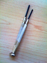
I don’t have any documentation that covers this. Instead, I took some tiny screwdrivers I had scattered in my toolbox, placed them in order from largest to smallest, and inserted them into the plug until I found the one that was just a little bit too big, and the one just smaller that managed to fit. I taped those together and brought them to the electronics store, where I used them to find a matching connector and two matching power sockets.
While at the store, I also purchased some wire, a fistful of alligator clips, and an extremely cheap and flimsy piece-of-crap voltmeter for 20 bucks.
A Voltmeter
If you’re going to embark on a project like this, you must obtain a voltmeter. Working on electronic devices without a voltmeter is like cooking without a sense of taste. You’ll follow the recipe and things will look just fine, but afterwards you’ll discover that you dumped two cups of salt into the cookie dough. Those cookies would go in the trash. Apply too much voltage to a component, and you’ll be throwing that component into the trash. A 20 dollar voltmeter pays for itself quickly, will grant you confidence, and will teach you about electricity as you work.
Not difficult at all. If you’ve ever played a kid’s game called Operation, using a voltmeter will be no problem for you. And hey, this is the internet, built on a foundation of geekery. You have many tutorials to choose from. Here’s a good one. And here’s a good companion to that one.
If cheap is the word, head to Radio Shack. The voltmeter in that link is about the same as the one I used. It’s the sort of product you’d expect to come tumbling out of a vending machine.
First Soldering
Okay, can’t avoid it any longer. It’s time to bust out the soldering iron.
I sympathize. Soldering irons are one of those specialized tools that are only used for one thing, and if you have to go buy a soldering iron for this project, you might never use it again.
But on the other hand, a soldering iron is not very expensive as special tools go. There are kits available for about 20 bucks – about the price of a hammer. And if you’re a hobbyist – which I assume you are, since you’re bothering to read this page – then you’ll find the experience worthwhile, and the skills useful.
Twisting things together will get you pretty far in the realm of wiring, as long as your project doesn’t move around much. But when you anchor your handiwork to a bicycle and go bouncing over potholes, the parts you’ve twisted together will unravel, loosen, or break. If you want something that charges batteries from a dynamo and has a USB port but you don’t want to deal with any wiring, you should purchase the DynaLader USB2, wrap it up in a good layer of tape, and call it a day. Don’t worry, I won’t be offended.
If you want something better than what the DynaLader offers, you’ll need to wire parts together. Twisting won’t be adequate. So take the plunge with me, and get hold of a soldering iron. Perhaps your workplace has one, or your neighborhood geek. He can probably be plied with chocolate.
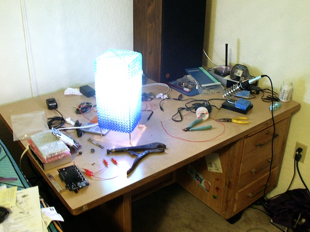
The important things to have at a soldering station are:
- A soldering iron (duh)
- Some solder (mmmyep)
- A really bright light you can move around to eliminate shadows
- A very steady third arm growing out of your chest (or, barring that, a table-mounted vise). Or a large pair of vice-grips from a hardware store. These can hold small things in place and you can rotate then, tilt them, move them around on the desk, and work around them easily.
- A pair of wire clippers for biting off chunks of spare metal on sloppy solder-work.
- Ventilation to blow fumes away from the face of the person at work, so the components don’t sprout little claymation eyeballs and go walking around a-la Better Off Dead.
Burning things in general produces carcinogenic smoke. If you get the smoke in your eyes or lungs, it hurts like hell, and pollutes the interior of your body. Toxicity and exposure level are the factors to consider.
As far as solder fumes go, they are pretty toxic. More toxic than sticking your face over a campfire, but less toxic than sticking your face in front of the tailpipe of a freshly started car. If you’re going to be soldering things every day for hours, you can do yourself a favor by constructing a makeshift fume hood, like the one in this tutorial. But if you’re going to be soldering things for only a couple of hours a year, the fume hood may not be a worthy use of your time. Just solder near a couple of open windows and try blowing gently on the part you’re soldering, to keep the smoke out of your face. Blowing on the part will make it heat slower, but not by any amount you’d notice.
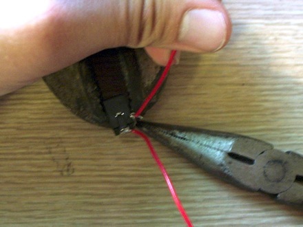
You may also find a pair of needle-nose pliers useful, for tightening loops of wire around things, like so:
Anyway, first I cut up some wire and began soldering it to the small alligator clips. I got help during this stage from Sherrila, who wanted to try her hand at soldering. She did an excellent job of it.
I was lucky enough to learn about soldering in a high-school electronics class. If you’ve got the time, I recommend you sign up for an entry-level class at a community college. It’ll be hands-on and a lot of fun.
But if you don’t have the time to get all Martha Stewart on this project, use this tutorial as your guide. It’s the best one I’ve seen on the web. And here are a few demonstration videos, courtesy of NASA’s Radio Jove project.
Not a gimmick, but there are tradeoffs. Personally I wouldn’t bother. Read this analysis, if you’re interested.
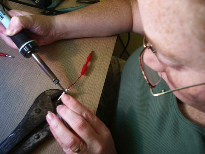
Next, I soldered wires onto the little DC power sockets. This is a little harder, but as long as you keep the iron pressed to the part and not to the solder, you’ll do alright.
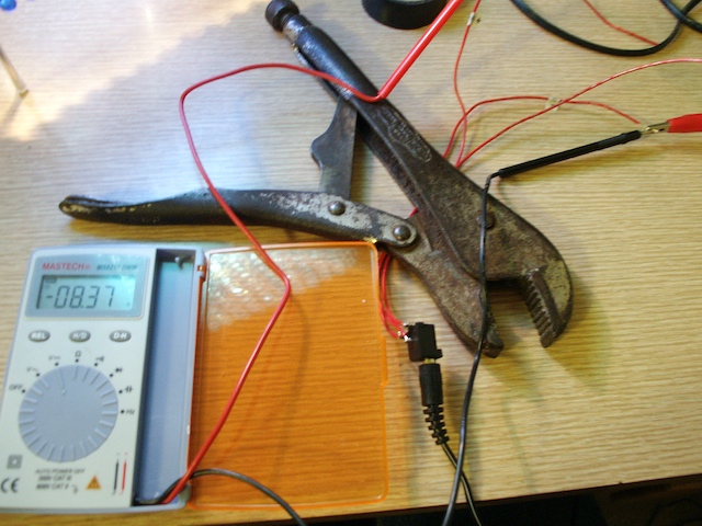
With a power socket wired up, the next thing I did was plug it into my wall adapter and test the voltages coming off the wires with my bargain-basement voltmeter. This way I could know, without a doubt, which of the three wires I should be using. I stuck little labels on them, and then wired them up to the TuneCharger board (with the power adapter unplugged for now).
Then I took one of my alligator-clipped wires, and two of my wires with alligator clips on just one end, and connected the batteries in series to the other end of the TuneCharger. I clipped the voltmeter onto the batteries to watch the voltage, and plugged the power adapter in.
The TuneCharger Reference Manual has a helpful diagram on pages 4.1 and 4.2. Match the plus signs with the plus signs on your batteries and power connector.
The TuneCharger blinked for a second, then started clicking very rapidly, and began charging up the batteries. As I watched, the voltage of the batteries increased by a few hundredths of a volt. Nice and smooth.
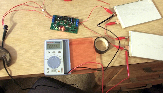
On the heels of that success, I unplugged the power adapter and plugged in the cable leading from my wheel generator, then gave the wheel a spin. The TuneCharger lit up, the lights changed to “charging” status, and it began to click. Slower than with the wall adapter, of course. But clicks are good.
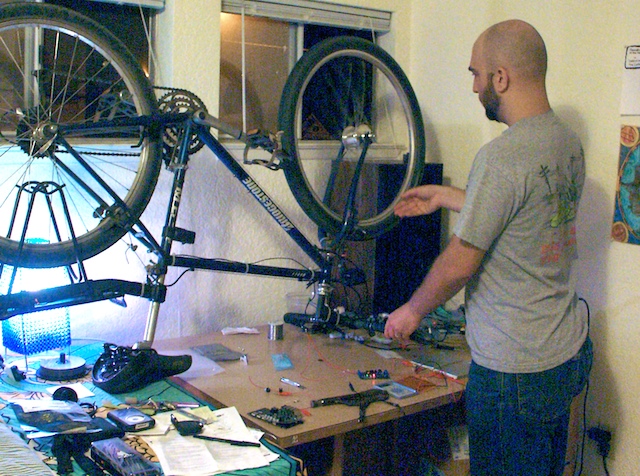
Looks like I’ve got the charging side of things covered. That was easy.
Now it’s time to get electricity back out of the batteries. To do that I’ll need a regulator circuit.
To Battery Output …

Very well written information. It will be helpful to everyone who usess it, including myself. Keep doing what you are doing – can’r wait to read more posts.